1000 L Agitated Tahini Mixing Tank
Full-cycle mechanical design of a batch mixing vessel for tahini, a highly viscous, shear-thinning sesame paste, from concept selection through detail design, finite element verification and manufacturability review, carried out for ArdeAfzal (Dezful).
Objective
Take a 1000 L batch vessel for a highly viscous, shear-thinning food paste from a functional requirements table through concept selection, detail design and independent finite element verification, sized and checked against process, structural, hygienic and safety requirements rather than drawn to a target volume alone.
- 1Batch working volume 1000 L ± 5%; agitator concept selected and verified for full-vessel turnover on a ≈60 Pa·s shear-thinning paste, with no stagnant zones.
- 2Product-contact construction meets EN 1672-2 / EHEDG hygienic design: Ra ≤ 0.8 µm finish, ≥ 3 mm internal corner radii, and a checked CIP spray-coverage argument.
- 3Shell, lid and drive shaft sized for internal pressure, external-pressure (vacuum) upset, bending, deflection and critical speed, with every governing check independently FEA-verified.
- 4Support frame carries the full filled weight (1763.6 kg) to the floor with a checked tip-over margin and a sized floor-anchor detail.
- 5Full GD&T datum scheme and tolerance stack-up across all five parts, closing the loop from the shell bore to the agitator's 5 mm running clearance.
The assembly
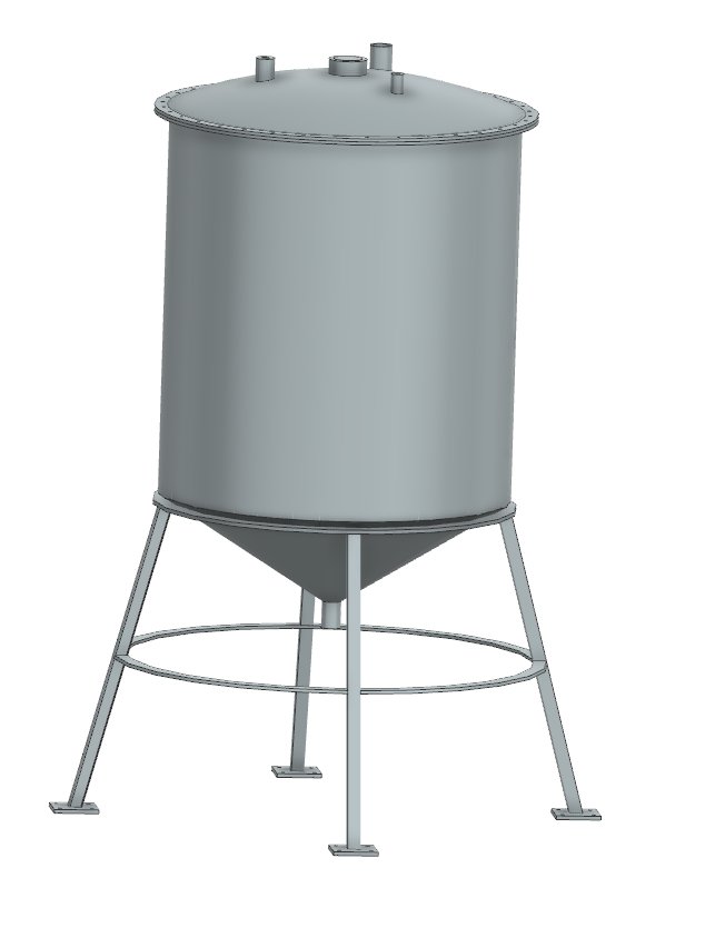
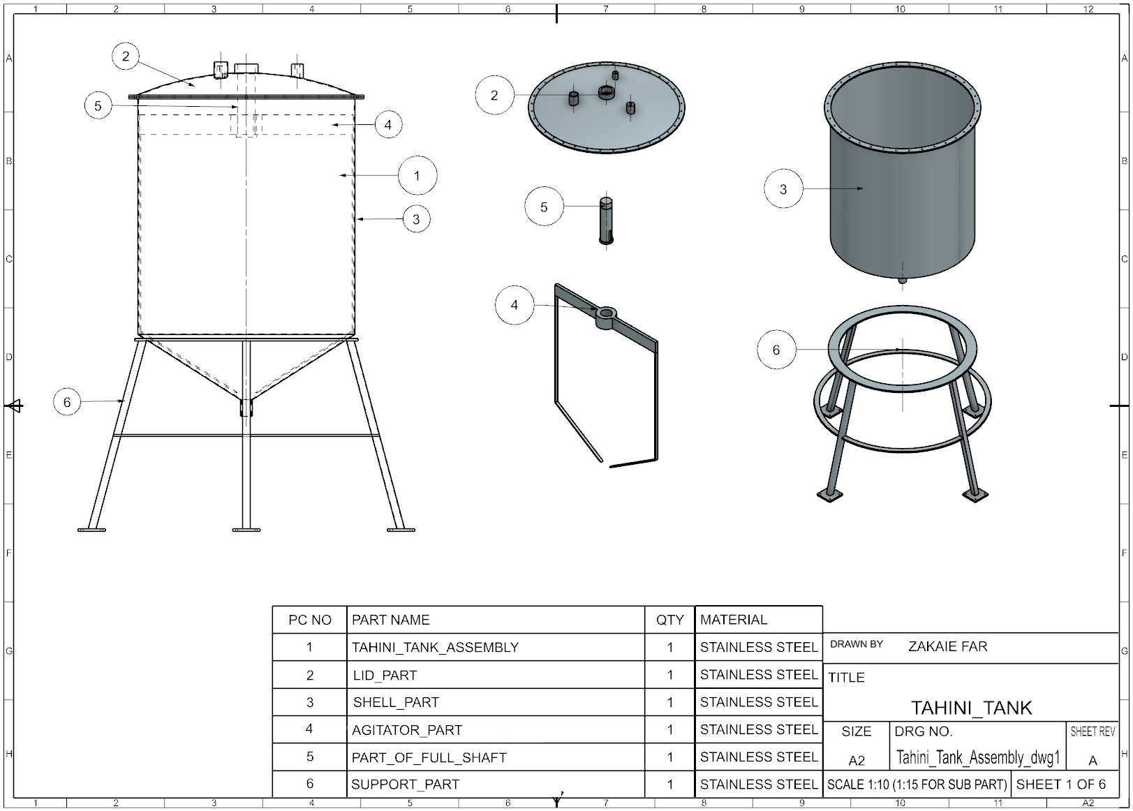
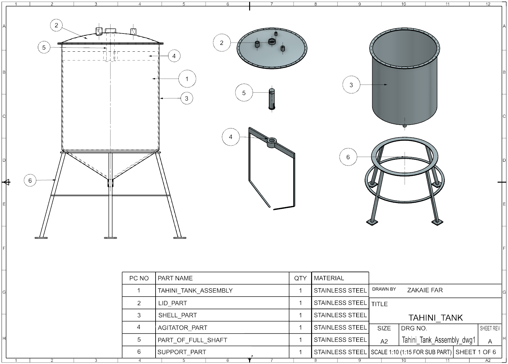
Five stainless-steel parts, each independently modelled, sized and toleranced, that come together as one vessel: the lid bolts to the shell through a gasketed 36-bolt joint, the shaft carries the agitator on two bearings and a double mechanical seal, and the whole assembly rests on a four-leg support frame.
The development of this assembly follows a structured engineering design process: Problem Definition and Requirements, Conceptual Design, Embodiment Design, Material Selection, Engineering Sizing and Design Basis, Detailed Design of the four individual components (including complete dimensioning and engineering calculations), FEA Verification, Manufacturability Assessment, GD&T and Tolerance Stack-Up Analysis, and Assembly and Close-Out. The sections that follow document each stage in turn.
Design Basis, Conceptual Design & Embodiment
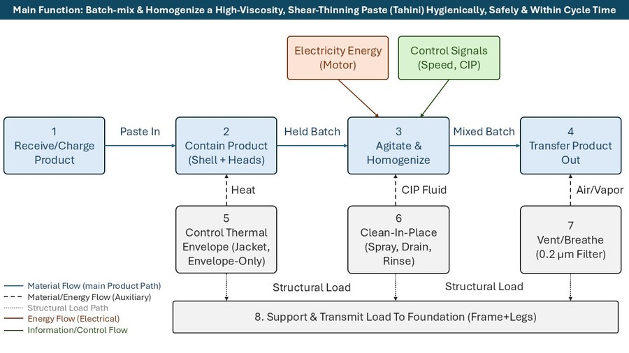
Before any part was sized or modelled, the vessel's shape, arrangement and material were decided and justified in writing: a functional decomposition and requirements table, a weighted concept-selection matrix stress-tested by sensitivity analysis, an embodiment freeze with six traceable decisions, an independent structural cross-check, and a two-stage material selection. Detail Design and the finite element verification that follow sized, modelled and checked what this stage decided.
Functional Requirements
| Requirement | Measurable objective | Wt |
|---|---|---|
| Batch working volume | 1000 L ± 5% | 5 |
| Mixing uniformity | Visually uniform paste; no unmixed pockets at wall, cone bottom or behind the scraper | 5 |
| Vacuum containment | Shell/cone survive full vacuum (CIP drain-down, blocked vent) with a stated margin | 5 |
| Product-contact surface finish | Ra ≤ 0.8 µm on all wetted surfaces | 5 |
| Crevice-free construction | Internal corner/weld radii ≥ 3 mm; no exposed threads in the product zone | 5 |
| Overpressure/vacuum protection | Relief device(s) sized and set (vacuum breaker ≈ −0.05 barg) | 5 |
17 requirements decomposed in total across five weight tiers (2 to 5); the six weight-5 "must" requirements are shown.
Conceptual Design: Concept Selection
Three agitator concepts were generated, screened for feasibility, and scored against the weighted requirements table above using a weighted decision matrix.
A single weighted matrix is not treated as sufficient justification on its own: the weights were perturbed twice, in two different directions, to test whether Concept A's lead would survive a reasonable engineer disagreeing with the baseline weighting. Concept A wins the baseline matrix and a mixing-performance-weighted variant decisively, and only loses in a variant that requires suppressing two need-linked criteria below a defensible floor. Concept A, the anchor-and-scraper agitator, is confirmed for Detail Design.
Embodiment Design: Arrangement Freeze
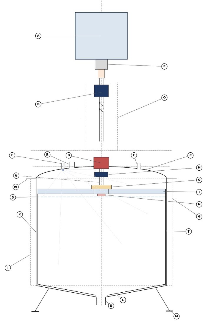
Embodiment Design freezes the physical arrangement, the topology of how the major components are positioned and connected, that Detail Design then sizes, models and simulates. Six decisions are frozen as the baseline; reopening any of them in Detail Design requires a documented reason, not a silent redraw.
- 1Drive & shaft support: top-entry gearmotor; two-bearing shaft (upper pillow block + lower guide bearing at the product line).
- 2Shaft seal: double mechanical seal, EHEDG hygienic class, at the cover penetration.
- 3CIP / spray layout: single top-mounted spray ball; wall-coverage argument accepted, arm/blade-surface coverage carried forward as an open item.
- 4Vent / breather: 0.2 µm hygienic filter, cover-mounted, isolated from the spray path.
- 5Jacket / gearbox / motor: simplified envelope volumes, no internal detail.
- 6Support frame: four-leg welded tube frame, ring-borne, levelling feet; bracing finalised as a mid-span ring during Detail Design.
Structural Configuration Justification
The structural configuration was selected and frozen using a weighted matrix and a qualitative arrangement freeze. This step re-examines it at a finer grain, part by part, using a two-level method: a per-part morphological screen and, where two or more variants survive, an independent Analytic Hierarchy Process (AHP) grading.
Only the bottom shape and the support-frame type had genuine multi-way competition; every combination of their surviving variants was checked for part-to-part compatibility before scoring, not a chosen subset. The cone bottom plus four-leg frame combination ranks first, ahead of the runner-up (cone plus three-leg) by roughly 15%, confirming independently the same configuration already selected in 3.2 and frozen in 3.3.
Material Selection
Applied independently to the three components whose governing failure mode differs: the shell (external-pressure buckling), the shaft (torsion/bending strength), and the agitator blades (bending strength, wear-exposed). Stage 1 derives an Ashby-style index directly from each component's governing physics; Stage 2 weighs the Stage-1 survivors against the project's own weighted requirements using a QFD-style scoring method.
Corrosion resistance is enforced as a non-compensatory hard screen before Stage 2 scoring: a minimum PREN ≥ 23 is required regardless of how well a candidate scores elsewhere. 304 stainless (PREN 18) does not clear this threshold and is eliminated; 316L (PREN 24) and 2205 duplex (PREN 35) both proceed to Stage 2 scoring.
| Component | Selected material | QFD4MAT final score |
|---|---|---|
| Shell | 316L | 3.176 vs. 2.824 (2205 duplex) |
| Shaft | 316L | 3.248 vs. 2.752 (2205 duplex) |
| Agitator blades | 316L, optional wear treatment at the scraper edge | 3.248 vs. 2.752 (2205 duplex) |
Duplex's real structural advantage is small at the shell (≈3.7%, since buckling is a stiffness-governed mode where the two alloys are close) and not needed at the shaft or blades, where 316L already carries comfortable margin. 316L is selected throughout the product-wetted train; a 2205 duplex or hardfaced scraper edge is flagged as the most defensible upgrade path if wear, not strength, becomes the limiting factor in service. Engineering sizing itself, turning these decisions into governing numbers, is covered in Design-Basis Sizing (05).
Method
Tahini behaves as a shear-thinning (pseudoplastic) paste: its apparent viscosity depends on the shear rate the agitator itself generates, a circular problem that the Metzner–Otto correlation resolves by treating the impeller as generating one characteristic shear rate proportional to its speed.
- All CAD modelling and drafting carried out in Siemens NX; structural and modal simulation in ANSYS Mechanical, cross-checked against Siemens NX Nastran.
- Every governing hand calculation, covering torque, bending, buckling and discontinuity stress, was independently re-verified by finite element analysis before being signed off.
- Each part is modelled in NX using construction logic that mirrors its actual fabrication: the shell and lid as single Revolve features from one connected sketch profile, nozzles and bolt holes as Pattern Features rather than repeated sketches, and the support-frame rings as a Revolve of the legs' own SHS cross-section.
- The drive shaft is checked against four independent failure modes at its governing sections: torsion and keyway stress concentration, combined bending and torsion, deflection and critical (whirling) speed, and fatigue under the Modified Goodman criterion.
- Design basis: EN 13445-3 (pressure vessels), EN 1672-2 / EHEDG (hygienic design), ISO 1101 (GD&T), ISO 21940-11 (rotor balance).
- Purchased components, bearings, mechanical seal, coupling and gearmotor, are sized by their calculated interface loads and dimensions, then checked against real catalogue references (SKF, John Crane, KTR, SEW-Eurodrive) as a starting point, not a final selection.
Design-basis sizing
Single source of truth for the governing sizing results: the numbers Detail Design built from and Finite Element Verification (07) checked.
| Quantity | Governing value | Basis / margin |
|---|---|---|
| Working volume | 1013.7 L | vs. 1000 L ± 5% target, met |
| Agitator power / motor | 4.06 kW calc. / 7.5 kW installed | ≈85% margin, covering rheology uncertainty |
| Gear ratio | 58:1 | 1450 rpm motor → 25 rpm agitator output |
| Shaft diameter | Ø90 mm (revised from Ø80 mm) | FS 1.29 hand-calc / 1.17 FEA, torsion + keyway, governing |
| Shell wall thickness | 4 mm | FEA FS 3.74× vs. full-vacuum fault (cylinder governs, not the cone) |
| Agitator arm section | 100 × 25 mm flat bar | FS 1.99 at the root fillet (FEA) |
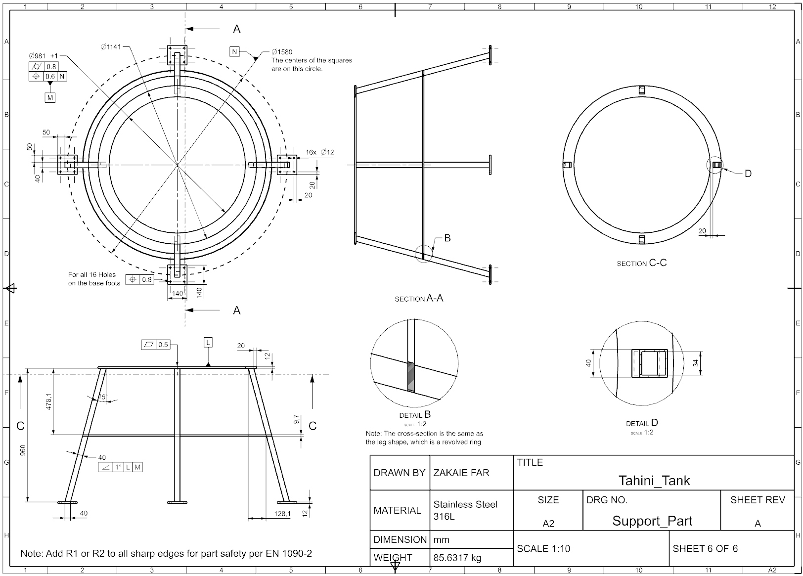
| Support-frame legs | 40×40×3 mm SHS, 4 off | FS 44.9× Euler buckling; FS 1.12× base friction (as-built) |
| Total filled mass | 1763.6 kg | NX-reported component masses + 1000 L product at 1200 kg/m³ |
Results
Every governing hand calculation was independently re-verified by finite element analysis. Three results changed the released design; the rest confirmed it, several with a wider margin than the hand calculation itself predicted.
Governing safety factor by verification check
Factor of safety (FS) at the governing failure mode, hand-calculated then FEA-verified. Hover a bar for detail.
| No. | Function verified | Result | Status |
|---|---|---|---|
| 1 | Contain product: internal + external pressure | FEA FS 3.74× vs. full vacuum | Verified |
| 2 | Agitate & homogenise: shaft + agitator | FEA FS 1.17–1.99 across governing checks | Verified, tight margin |
| 3 | Support & transmit loads: frame | Tip-over FS 10.5×; base friction FS 1.12× | Verified, tight margin |
| 4 | Clean-in-place: spray coverage | ≈94% estimated wall coverage (analytical) | Pending physical validation |
| 5 | Vent / overpressure protection | Breaker set point cross-checked vs. FEA | Verified |
Finite element verification
Four studies, each modelling the real geometry, fillets, keyways and all, rather than the idealised sections the hand calculations use, and each converged and mesh-checked before its result was accepted.
Drive Shaft: Torsion, Bending & Critical Speed
Survive the full motor-rated design torque (2722 N·m, a 1.76× overload factor over the process duty) at a keyed cross-section, stay within the 5 mm running clearance under the agitator's bending load, and keep the critical (whirling) speed at a large margin over the 25 rpm operating speed.
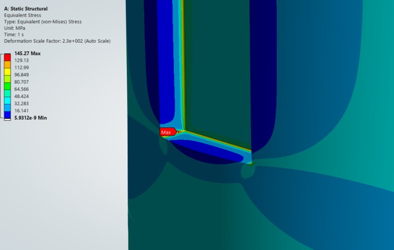
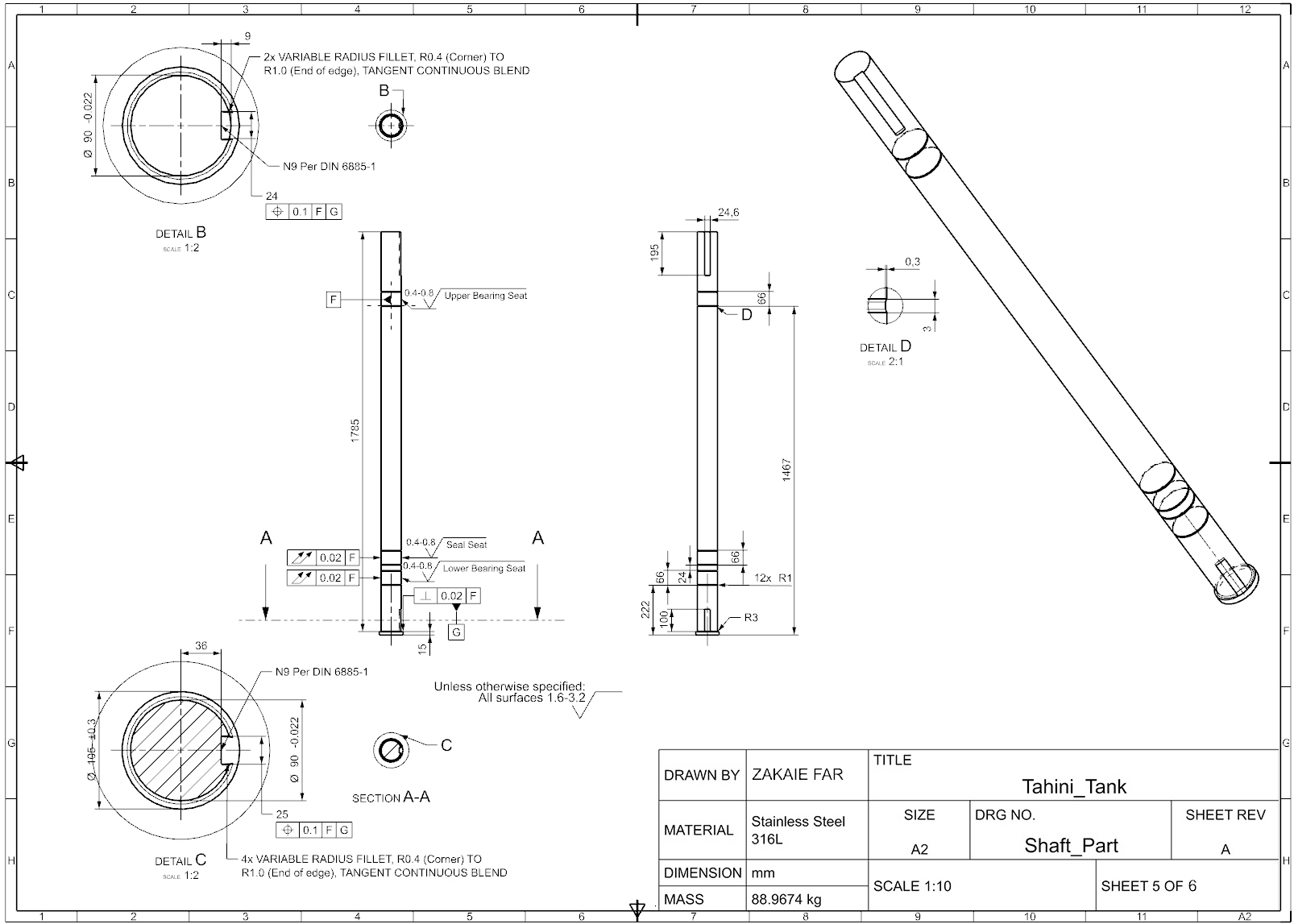
The hand calculation (FS 1.29) missed a real 3D effect: the FE model found the true peak stress at the open end of the drive-end keyway (FS ≈ 0.83 at the original geometry, predicting local yielding). A variable-radius fillet, holding the DIN-constrained 0.4 mm along the keyway root and tapering to a larger radius at the open corner, resolved it to FS ≈ 1.17, and was carried into the released drawing.
Agitator Arm: Root Bending at the Hub Weld
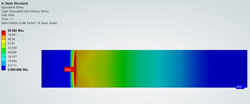
The anchor arm's root, the hand-calculated margin found anywhere in the project (FS 2.28, idealised as an untapered flat bar), needed FEA confirmation before accepting the as-designed section without a thicker or tapered root.
A symmetry model of the hub-and-arm weld, loaded with a drag pressure calibrated to the same root moment as the hand calculation, confirms the untapered 100×25 mm arm section: no redesign required. The fillet's modest stress concentration (Kt ≈ 1.15) explains the 15% gap to the hand calculation's uniform-section estimate.
Tank Shell: External-Pressure (Vacuum) Buckling
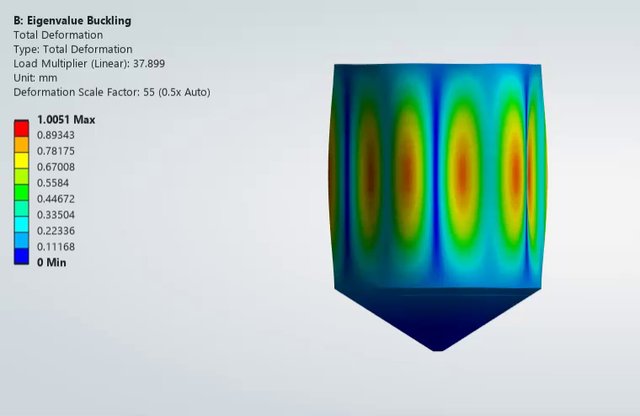
The 4 mm shell wall is sized against a vent-limited vacuum event, not an unmitigated full vacuum. The classical hand-calculation screen had flagged the cone, not the cylinder, as the weak point, with a margin below the vacuum breaker's own set point. This called for a full eigenvalue buckling analysis of the real geometry.
Contrary to the hand calculation's own expectation, the governing mode is a five-lobe circumferential wave confined to the cylinder, and the cone shows essentially zero participation. Its continuously decreasing radius makes it intrinsically more buckling-resistant than the flat effective-cylinder approximation used for screening suggested; the hand-calc bound is confirmed conservative, not a close call the FEA happened to clear.
Girth-Weld Junction: Discontinuity Stress
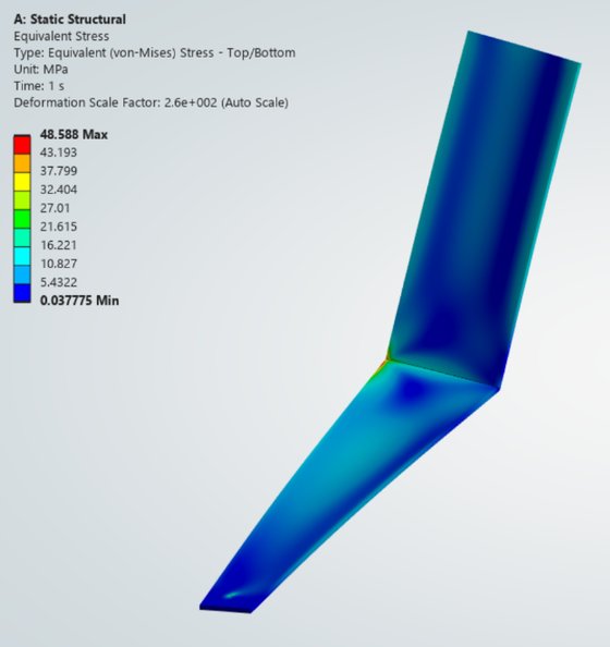
The cone-to-cylinder junction has a 58.8° half-angle, well past the ≈30° threshold at which pressure-vessel codes require either a knuckle radius or a formal special analysis, and this design uses neither. An axisymmetric wedge-sector model quantifies the local bending stress the junction's sharp geometry produces under internal pressure.
Note: The reported stress value of 48 MPa should be treated with caution, as it occurs at a sharp geometric corner/edge. Stress concentrations at such locations can result in a localized, non-physical FEA singularity; therefore, the peak stress is not considered representative of the actual structural response.
Based on these findings, the FEA-derived peak is roughly five times lower than the conservative hand-calculation screen (56.7 MPa). The symmetric edge-shear-split approximation the hand method relies on is a poor fit for this vessel's unusually steep half-angle. No knuckle radius or thickness increase is required on structural grounds.
Final Drawings
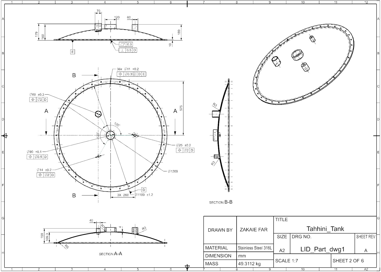
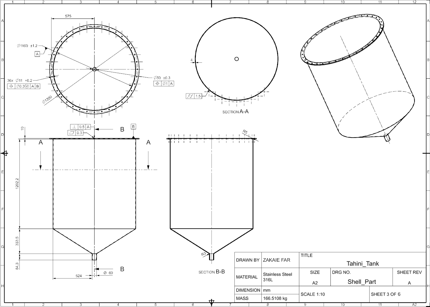
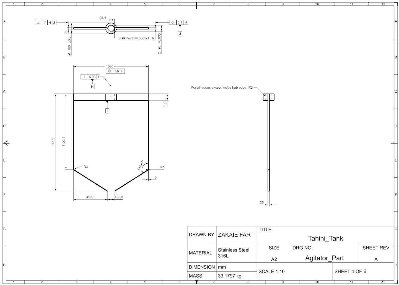
The drawings below carry each part's final dimensions together with the datum scheme, feature control frames and general tolerances developed in Manufacturability, GD&T & Tolerance Analysis, released as a six-sheet package.
Verifications
Project close-out, checked three ways: sub-function by sub-function, risk by risk, and requirement by requirement.
Functional Check
The functional decomposition from Overview (01), closed out: each sub-function checked against what was actually designed, sized and verified.
Show all 7 rows
| No. | Sub-function | Built & verified | Status |
|---|---|---|---|
| 1 | Receive / charge product | Entrance nozzle sized and located on the lid (Ø60/Ø70 mm) | Built as planned |
| 2 | Contain product | Internal-pressure FS ≈15×; external-vacuum case FEA-confirmed FS 3.74×, with the cylinder, not the cone, governing | Verified, FEA corrected the governing location |
| 3 | Agitate & homogenise | Shaft FE-verified across two load cases plus modal; arm FE-verified at FS ≈1.99, the structural margin in the project | Built and verified |
| 4 | Transfer product out | Drain nozzle sized on the cone (Ø50/Ø60 mm) | Built as planned |
| 5 | Clean-in-place | Top-mounted static spray ball, ≈94% estimated wall coverage; moving-surface coverage still open | Designed, validation pending |
| 6 | Vent / breathe | 0.2 µm hygienic vent filter; vacuum-breaker set point cross-checked against the FEA buckling margin | Built and verified |
| 7 | Support & transmit loads | Leg buckling FS ≈44.9×, tip-over FS 10.5×; as-built friction margin thin at FS 1.12×; M10 wedge anchors raises the margin to 5.5× | Verified, anchor upgrade recommended |
Risk Register: Final Disposition
The nine product risks scored at concept selection (03), closed out: what actually mitigated each one across Detail Design, FEA and Manufacturability.
Show all 9 rows
| No. | Risk | Evidence | Disposition |
|---|---|---|---|
| 1 | Shaft bending/whirling unverified | FE-confirmed FS 1.17–1.97; critical-speed margin 619×, after a fillet fix the FEA itself found | Mitigated by design |
| 2 | Shell vacuum buckling | FEA FS 3.74× vs. full vacuum; cylinder governs, not the cone the hand-calc flagged | Mitigated by design |
| 3 | Hygienic design detail unspecified | Corner/weld radii and surface-finish requirements verified compliant | Mitigated by design |
| 4 | Agitator torque overload at startup | 1.76× torque overload factor built into the shaft/motor sizing | Mitigated by design |
| 5 | Mechanical seal leakage | Double mechanical seal specified, EHEDG-hygienic class, with a 0.02 mm total-runout GD&T requirement | Mitigated by component selection |
| 6 | Weld/crevice contamination | Weld-quality and fillet/weld-toe radius requirements verified compliant | Mitigated by design |
| 7 | Frame instability / under-sized anchoring | Leg buckling FS ≈44.9×, tip-over FS 10.5× | Mitigated by design |
| 8 | Tolerance stack-up interference at the wall clearance | Every governing chain, bolt circle, nozzle position, overall height, keyway fit and wall clearance, checked and passes | Mitigated by design |
| 9 | Agitator imbalance vs. ISO grade | Calculated eccentricity ≈7% of the ISO G6.3 permissible budget | Mitigated by design |
Requirements Checklist
The specification table from Overview (01), checked item by item against final status at project close-out.
Show all 13 rows
| No. | Requirement | Basis | Status |
|---|---|---|---|
| 1 | Batch working volume 1000 L ± 5% | Sized to 1013.7 L, +1.37%, within band | Met |
| 2 | Mixing uniformity, no unmixed pockets | Anchor+scraper selected for full-vessel turnover; uniformity itself needs a commissioning trial | Partially met |
| 3 | Vacuum containment, stated margin | FEA-confirmed FS 3.74× against full vacuum | Met |
| 4 | Internal pressure allowance | Hand-calculated FS ≈15× against the stated excursion case | Met |
| 5 | Shaft/seal dynamic runout ≤ allowable | 0.02 mm runout specified and flowed into GD&T; not yet checked against a named seal's actual limit | Partially met |
| 6 | Agitator balance to ISO 21940-11 grade | Grade G6.3 analytically confirmed with large margin; physical balance check not yet performed | Met, pending confirmation |
| 7 | Structural design life ≥10 years | Shaft fatigue FS ≈11.6× confirmed; the agitator arm's cyclic stress is a stated limitation, not fully quantified | Partially met |
| 8 | Support-frame stability, no uplift/tip | Tip-over FS 10.5×, leg buckling FS ≈44.9×; as-built base-friction margin thin at FS 1.12×; M10 wedge anchors raises the margin to 5.5× | Met, with a caveat |
| 9 | Surface finish Ra ≤0.8 µm | Specified and verified compliant | Met |
| 10 | Crevice-free construction, radii ≥3 mm | R3–R5 minimum radii specified and verified compliant | Met |
| 11 | CIP cleanability, validated spray coverage | Self-drain slope ≈33° exceeds the 3° minimum; spray coverage ≈94% estimated, full validation deferred | Partially met |
| 12 | Vent filtration, 0.2 µm filter | Specified on the vent | Met |
| 13 | Overpressure/vacuum protection | Vacuum-breaker set point specified and confirmed against the FEA buckling margin | Met |
Engineering judgment & recommendations
Beyond the pass/fail results, the verification campaign surfaces where the design has room and where it genuinely does not.
⚠ Watch the support-frame's base-friction margin (1.12×)
With the frame's four feet simply resting on the floor, only friction resists the legs' outward splay thrust, and a food-processing floor exposed to sesame-oil residue is a realistic case for a lower coefficient than the conservative 0.30 already assumed. The frame's four pre-drilled floor-anchor holes are provided for exactly this; fitting the recommended M10 wedge anchors raises the margin to 5.5×+ and should be treated as a required installation step, not an option.
FEA changed the released design, not just confirmed it
The shaft's keyway-corner redesign, the shell's corrected buckling-governing location, and the agitator arm's confirmed-adequate root section are three independent, real findings, evidence that the verification campaign was doing genuine engineering work rather than a formality bolted on at the end.
The rheology assumption is the single largest open item
The tahini's shear-thinning parameters (n≈0.4, K≈150 Pa·sⁿ) are literature-representative values, not a measurement on the actual product, which is why a 50% design margin is carried through the motor sizing. A rheometer run on the real product, ahead of any scale-up, would replace that buffer with a verified number.
A full code calculation would close the last gap to certification
The shell's external-pressure case is currently closed by an FEA eigenvalue result, not the full EN 13445-3 clause 8 code calculation named as the alternative path. Running it as an independent cross-check would close the gap between this pilot's screening methodology and a certified design.